Trusted by ANSPs and training institutions around the world


How It Works
A self-contained solution
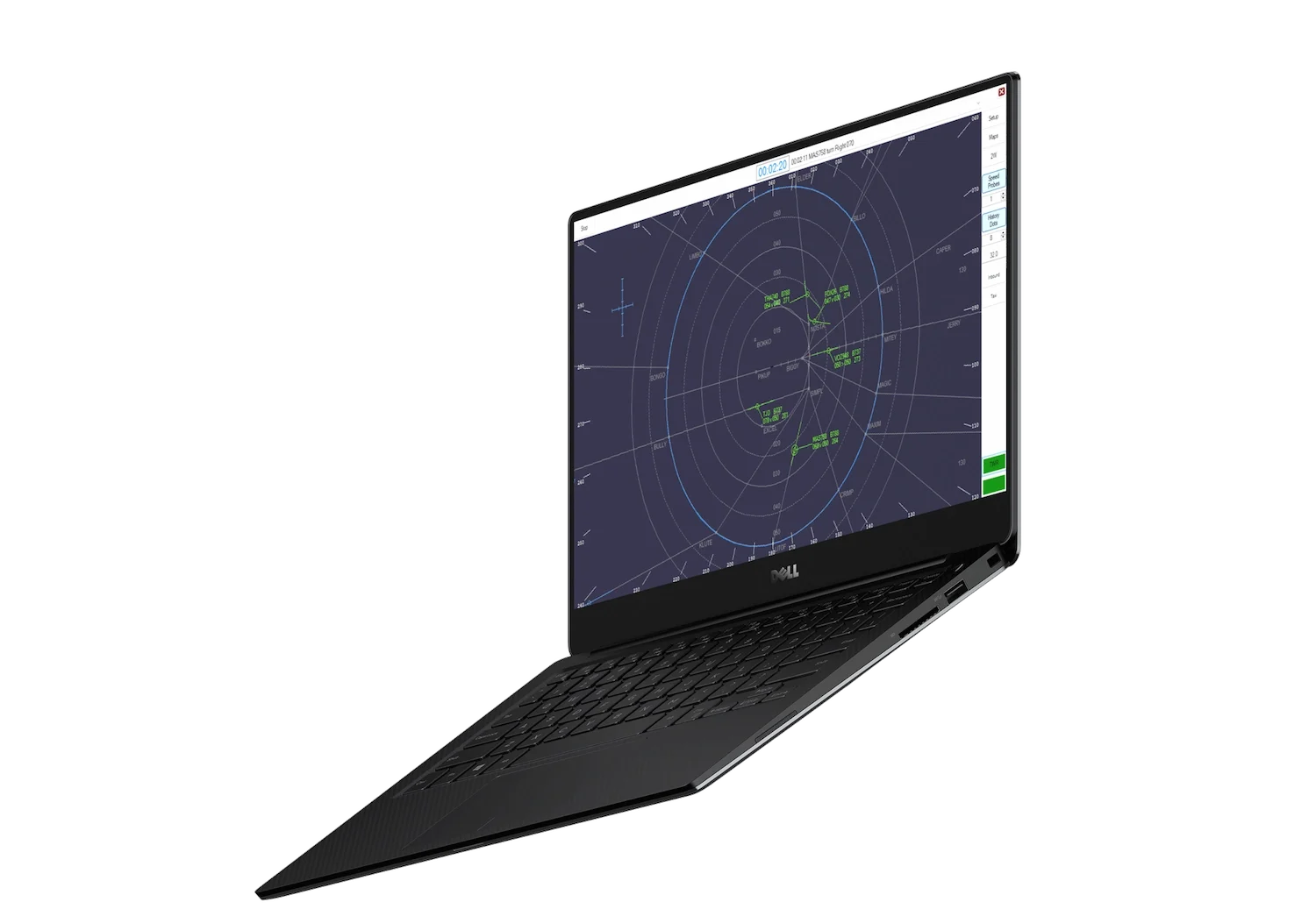
Take a tour of the teaching system delivering practical surveillance training to any PC without the need for instructor oversight or specialised hardware.
Expert Teaching
Carefully curated video lessons and training exercises targeting essential skills in surveillance control.
Standalone Simulation
The personal teaching simulator. Featuring independent operation and automatic performance tracking – no pseudopilots required.
Flexible Delivery
Access training anywhere with Control Zone, the cloud hub for Visual Vectoring courseware and time-saving administration tools.
How we help
Your training capability multiplier
Access equals opportunity. Discover how on-demand simulation can elevate training, lower costs and expand curriculum at your organisation.
ANSPs and ATC Training Providers
Improve Outcomes
Provide a low-pressure environment for trainees to develop confidence and consolidate core skills during early training.
Optimise Infrastructure
Enhance the availability and efficiency of existing simulator equipment.
Empower Instructors
Equip the experts with data-driven insights into student performance and additional opportunities for one-on-one mentorship.
Higher Education & Universities
Lead the Field
Provide every student with access to industry standard simulation training at low cost and without the need for specialised equipment.
Flexible Delivery
Teach your way with a cloud delivery platform that supports remote learning and a range of on-campus applications.
Readymade Courseware
Simplify curriculum design with a suite of readymade surveillance courses designed by experienced instructors.
TESTIMONIALS
What our Partners say
"Our partnership with Visual Vectoring has led to a change in the way Air Traffic Control instruction is conducted at the largest aviation universities in the world and has assisted in the training of over 4,000 students of ATC - the next generation of controllers.”
Ivy Liu - General Manager
Beijing Connected Vision Technology
"VV Enroute Training has been a popular elective of our Engineering and Technology Programs since 2014. The software helps our students acquire skills for air traffic management and prepares our graduates to qualify for the National Cadet Program for Air Traffic Controllers.”
Engr. Jose Eduardo S. Valdez - College President and COO
PATTS College of Aeronautics
"Visual Vectoring provided us with a complex, custom simulation package, allowing ATS to deliver high fidelity APP P training to our client. They are extremely responsive to work with and I would have no hesitation in recommending VV products to any prospective customer."
Mike Lockwood - Managing Director
Air Traffic Solutions
"VV Enroute was easily integrated into our curriculum and provides valuable skills training and phraseology practice for students preparing for the Phillipines Air Traffic Control program."
Ruffa Paycana - Coordinator, Aviation Communication
Philippine State College of Aeronautics


Become a Partner
Join a global community of institutions transforming their teaching capacity with on-demand simulation training.
Get started todayCourses
A comprehensive curriculum at your fingertips
Select from a suite of courses delivering foundational skills training across a range of surveillance disciplines.
View Courses

Training thousands of prospective Approach Controllers how to manage a busy sequence to the runway.

Covering fundamental skills in surveillance control – ideal for students experiencing ATC for the first time.

Teaching the complex skill set required to manage an arrivals sequence with the use of holding, vectoring and time requirements.

A training capstone: teaching the simultaneous management of mixed departures and arriving traffic.

The most effective way to deliver targeted competency training for the response to a compromised separation event.
Helping thousands of students around the world
2750+
concurrent users
15
institutions
9000+
students and controllers trained
Latest news & insights
Stay up to date with the latest developments from Visual Vectoring and our training partners